Abstract
Introduction
One of the things that immediately comes to mind is 3D printing the cookie cutter. And indeed, quite a few people have done so already. Also, the idea of building something like a cookie cutter creation tool is not new. However, this tool (and others alike) suffer from the fact that judging the physical dimensions of a drawn shape remains difficult or that their expressiveness is rather limited.
- design cookie shape by bending a wire or drawing a thick black line
- place/draw the outline on an A4 sheet of paper
- take a photo of the outline and extract, smooth a polygon
- convert outline into a printable cookie cutter

Figure 1: the design process demonstrated with a user-designed shape: (a) designing the cookie cutter shape by bending a wire, placing it on an A4 sheet of paper and taking a photo of it (b) filtering the photo by binarizing it, extracting the paper sheet corners, and using a canny edge detector (c) constructing a 3D model using OpenSCAD and extracted polygon (d) printing the cookie cutter on a 3D printer
Shape definition
Many ways of defining 2D shapes are described in literature. From sketch based interfaces to more traditional 2D CAD systems. All of those approaches suffer from their disconnection to world they are designing for. It is hard to judge the dimensions and appeal of those virtual artifacts before they become physical reality.
Our approach in this work lets the user define the shape using a simple, tangible shape input controller: a piece of wire. Imagine there was something like a "cookie cutter band" that one could bend into the desired shape. Once bent, the shape would be fixed and additional struts would be introduced to strengthen the cutter. That’s exactly what this system does. The user bends a piece of wire into the desired shape and the system constructs a cookie cutter, which is then printed on a 3D printer.
Shape extraction
The wire shape has to fulfill a set of constraints, so that it makes sense as a cookie cutter:
- planarity: the wire has to be bent flat, much like the cutter itself is going to be. This constraint is also imposed by the application domain, as cookie dough is generally flat.
- not self-intersecting: a self intersecting cookie cutter would produce cookies which do not hold together as one piece – hence, we require the shape to be a simple polygon.
After bending the shape, the user places the piece of wire on an A4 sheet of paper and takes a photo of that assembly. The photo is then fed into this system which extracts the shape using computer vision. Since the outcome is going to be produced for the real world, the polygon has to be translated into real world units. We map the image to real world coordinates by detecting the corners of the A4 paper. This leads to the following processing pipeline (implemented in C++ using the OpenCV):
- threshold filter to binarize the image
- find paper corners and compute the homography
- warp perspective of the input image based on the homography
- canny filter the warped image
- erode the image to connect spurious lines
- find contours in eroded image
- select contour with largest area that is not the whole image
- if no contour is found, exit
- find center of the polygon using the enclosing circle
- approximate outline using Douglas-Pecker to smooth the polygon
Model creation and printing
The polygon coming from the shape extraction stage is then scaled into a smaller and a bigger version, which are assembled to form the cutter using CSG operations, implemented in OpenSCAD. Scaling a concave polygon to build an outline is not as straight forward as scaling a convex one. While a convex polygon can be adequately scaled by multiplying each vertex with a scalar value, scaling a concave polygon that way is unsuitable for creating the model (see figure 2, b). To properly scale a concave polygon  for our needs, we translate each
  by the edge normal
![\[\lambda\frac{\mathbf{n}}{\vert \mathbf{n} \vert}, \mathbf{n}=(\mathbf{p}_{i+1} - \mathbf{p}_i)\]](/media/writing/32leaves-1028-4.png)
with results as depicted in figure 2,c.
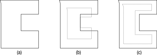
Figure 2: Scaling a concave polygon to create a thin outline: (a) the polygon to be scaled (b) the naively scaled version, drawn as dotted line (c) the properly scaled polygon
Discussion
We implemented this system using simple computer vision algorithms. While this implementation is sufficient in many cases, it is not particularly robust. The paper sheet corner detection does not always work and the whole process depends on proper parameter choice – parameters which are image dependent. A more sophisticated processing pipeline or some form of automated parameter choice could be explored.
Also, the line extraction depends on the characteristics of the shape being extracted. While the erosion stage somewhat mitigates this effect, e.g. glossy wires or "sketchy" are still unsuited for this system.
Also, the importance of real-time feedback could be explored. Is it enough to get feedback on the producability/constraint enforcement at discrete points in time, e.g. when we feed an image into the system? Or should the system provide continuous feedback? Also, what is the relationship between constraint system complexity and real-time feedback need?
Conclusion
In this work, we described the idea of using household items for modeling, specifically investigating wire as shape input sensor and A4 paper as fiducial marker. We implemented a system for designing cookie cutters as case study, targeting 3D printing as production technique. Our system is easy to use, as it is situated in the real world.
Download
The source code can be found here, including a few test pictures. I’ve only tested it on Linux, however, it should run on OSX as well. To compile/run the stuff run:
1 2 3 4 | tar xvfz contours.tar.gz && cd contours mkdir build && cd build cmake .. && make ./contours ../test4.jpg && openscad main.scad |